A few years ago, i started developing an interest in drones and robotics. I've always been interested in electronics and it's possibilities in combination with computers, but especially after the release of the Arduino and Raspberry Pi platforms it's never been easier to make your own electronic appliances/gadgets.
The popularity of drones, rovers and robots is quite obvious in these times, unfortunately also in more negative applications like wars and surveillance. I'm not going into that subject right now, this article is about peaceful hobby applications and i'm just a geek™.
When using boards like the Arduino or Raspberry Pi for communication with a device, usually you are limited to using bluetooth or wifi. This makes it great for indoor applications, but not for using it with a drone or rover. The solution for me was using a device i had in storage (for a while). My Flysky FS-I6 transmitter and some receivers. I bought these cheaply at some webshop a few years earlier. The range is around 1.5 - 2.0 km, which is a lot more than bluetooth and wifi.
There are ways to extend the range of bluetooth and wifi, one of which is using directed beams but they are a bit far-fetched for now. (i seem to remember a method which involves Pringles cans)
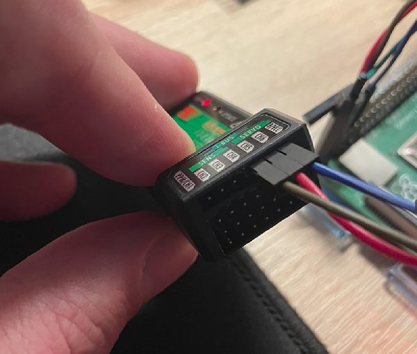
In order to make the transmitter communicate with the receivers, you need to bind them first. Long story short, you put the bind key on the FS-IA6B, power on the FS-I6 with the bind key pressed and it should bind the two together. You'll hear a short bleep to confirm.
A lot of devices have a serial connection, of which the Flysky receiver is no exception. A schematic tells me that the Ibus/serial connection is the top-right pin and the pins to the left of it are for power. For simplicity's sake i'm only going to process the data coming from the transmitter. There are ways to also include sensor and throttle data, but for now this will suffice. The voltage necessary is between 4.0 - 8.4V/DC. The Raspberry Pi's 5V should be enough. A few steps are necessary to enable the serial port on the Pi, you can read about it here. And here is a nice overview of the pins on the Raspberry Pi.
Connect the positive (red) wire to the +5V on the Pi (pin 2 or 4) and the negative (black/brown) on ground (pin 6). The serial connection is done to pin 10 (RX). You can simply 'screen' (or use another serial monitor) into your serial device (usually '/dev/ttyS0') and you will see data coming in. However, since Flysky uses the Ibus protocol, it's data is not yet usable. You'll probably see a lot of weird characters filling your screen. To interpret the data we need to use some programming. I'll use Python for now. The Ibus data stream is specific and somebody wrote a class/package for it, it can be found here

My very simple script prints the received values, you can see them change when using the transmitter. I'm currently still testing the limits so for now i've limited it to read and print a value every 50 ms. Theoretically the receiver sends signals at 1 ms, but the limit is 115200 bits/sec for this serial connection. Some fine-tuning will still be needed but that is not the purpose of this particular article.
from flySkyiBus import IBus
from os import system
from time import sleep

while True:
    system("clear")
    data = IBus("/dev/ttyS0").read()
    print(data)
    sleep(0.05)
Your output should be like this:

The data variable is a python tuple, it's values can be addressed like this: data[index number]. The first and second value is a static number, but you can find out which value corresponds to which button or stick by playing with it. I found that the rotary encoder VRA corresponds to the seventh value. That should be data[6]. The index starts at 0. An example use of two rotary encoders on your FS-I6 is:
data = IBus("/dev/ttyS0").read()
switch_vra = data[6]
switch_vrb = data[7]
The values from switches and throttles/sticks show a number between 1000-2000 so in order to work with them i'd recommend changing them to readable values. A switch can be a boolean or a numeric value (1,2,3) and a value between 1000-2000 can easily be converted to a percentage. I'll leave it up to you to decide. For the program to work it doesn't matter, but visually it can help explain the values better. Since i'm making an example to control a servo, conversion is necessary. The servo i'm using can rotate between -90° and +90°. So the lowest value of 1000 corresponds to -90° and the highest value of 2000 corresponds to +90°.
Some very basic math (yes, i've had to look it up... :-) used for calculating one scale to another gives us:
oldRange = oldMax - oldMin
newRange = newMax - newMin
newValue = ((oldValue - oldMin) * newRange / oldRange) + newMin
Which translates to this in python (quite literal):
oldRange = 2000 - 1000
newRange = 90 - -90
newValue = ((switch_vra - 1000) * newRange / oldRange) + -90
Ofcourse, above can be improved, but i left it like this for brevity and clarity.
Update: You can use conversion tools from gpiozero
With this quick calculation we can convert the values to degrees to drive the servo motor. The resulting number can be quite long (float values and all), so you probably want to cut some length off/round it. You can use the round function for that, again for simplicity's sake:
print(round(newValue, 2))I've reversed the value in the end for writing it to the servo, it depends on the servo orientation. This is the final program:
from gpiozero.pins.pigpio import PiGPIOFactory
from gpiozero import Device, AngularServo
from flySkyiBus import IBus
from os import system
from time import sleep

servo = AngularServo(18, min_pulse_width=0.0006, max_pulse_width=0.0023, pin_factory=PiGPIOFactory())

while True:

    data = IBus("/dev/ttyS0").read()

    switch_vra = data[6]
    switch_vrb = data[7]

    oldRange = 2000 - 1000
    newRange = 90 - -90
    newValue = (((switch_vra - 1000) * newRange / oldRange) + -90) * -1

    angle = round(newValue, 2)

    print(angle)

    servo.angle = angle

    sleep(0.00125)
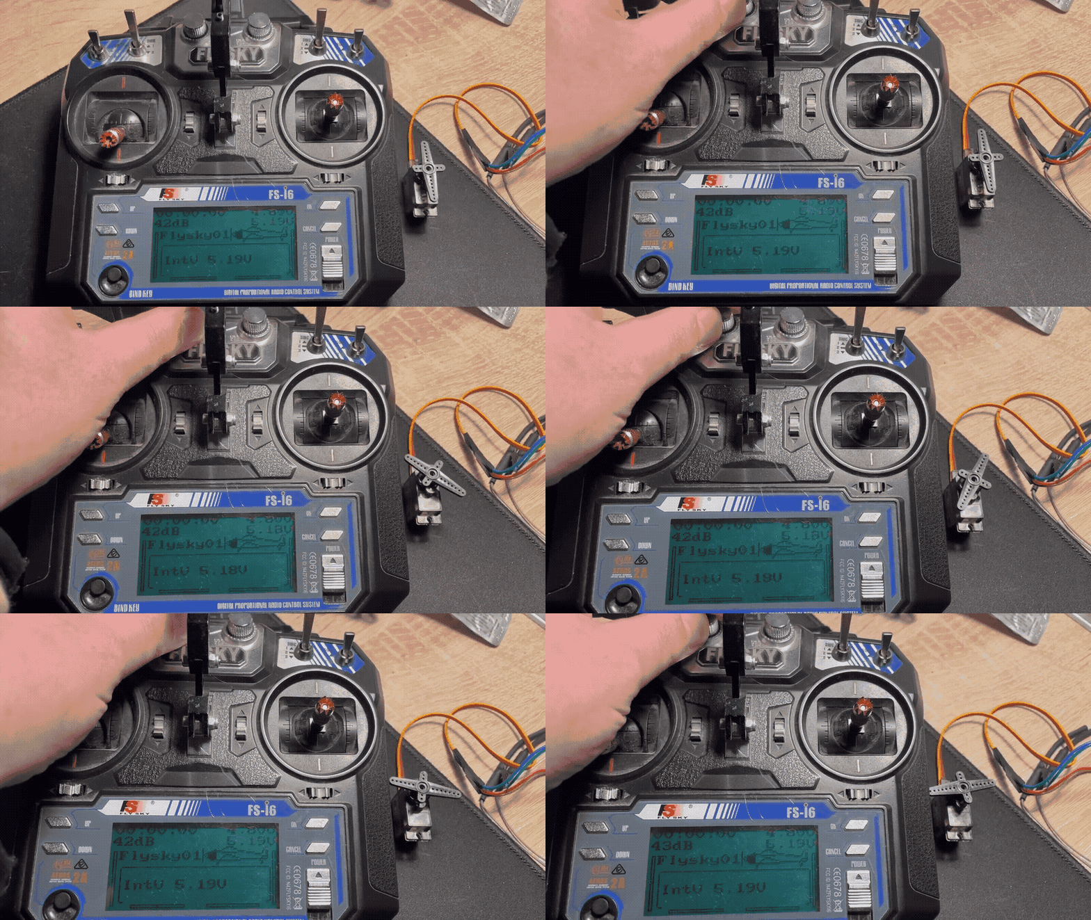
This should be the end result:

You can now start building your bot/drone/rover or whatever you want! I hope you can build some awesome stuff and enjoyed this small tutorial. Below are some sources for further reading.